24 January 2012
James Cutler, [email protected], KF6RFX
For awhile, I have been baffled by our inability to increase the maximum FM deviation levels of our Icom 910H. I first noticed this back on the QuakeSat mission where one of our 910 units had a max deviation of 2.5 KHz and the other 3.2 KHz. For typical GMSK modulation systems, a deviation of 3KHz is recommended. The lower deviation 910 was unable to transmit successfully to QuakeSat. Recently, I finally figured out how to do it, and it takes a relatively simple modification to the 910, a single surface mount resistor change.
At first, we thought the fix could be performed through a software-based configuration change to the 910. Icom has a great service manual that is readily available online. I have a hard copy that I purchased awhile back that is useful for viewing schematics. Page 5-17 describes how to change the maximum deviation. We tried this on several 910 units and while we could adjust the max deviation in this configuration mode, the unit would not exhibit the same max deviation during normal operation. We sent a unit back to Icom as well, and when it returned, we could not adjust beyond the max of ~ 3KHz.
After a few hours of careful study of the schematics (again, Icom has a great service manual), I realized the software deviation settings do not affect the high speed data path of the 910 through the MAIN and SUB data connections on the back. They only affect the ACC connections. You can see this in the lower left hand corner of the block diagram on Page 10-1, copied below. The “GAIN CTRL” element is for the non 9600 path.

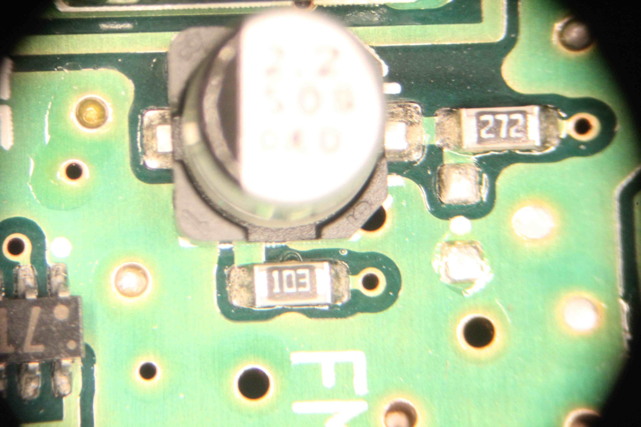
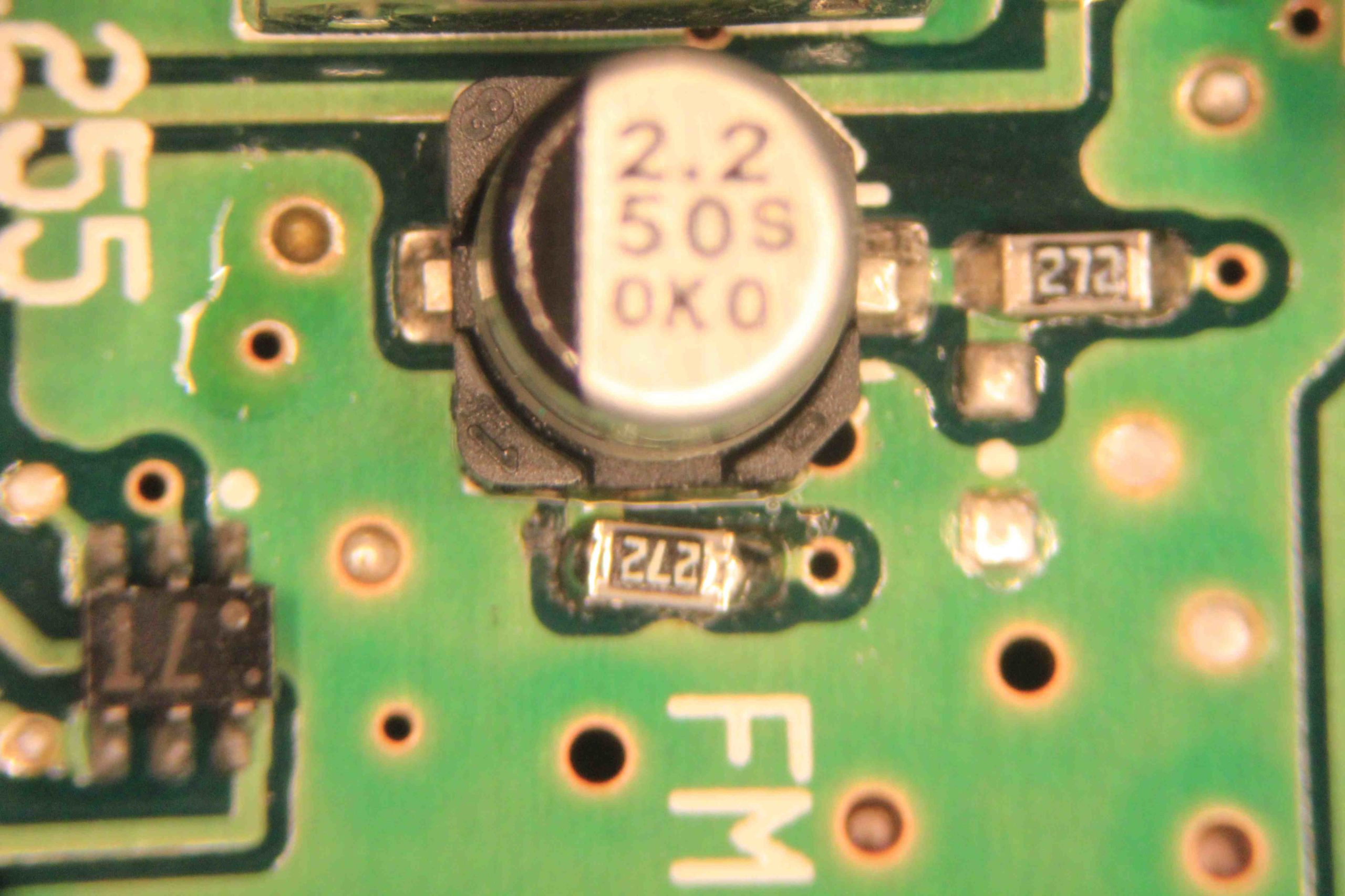
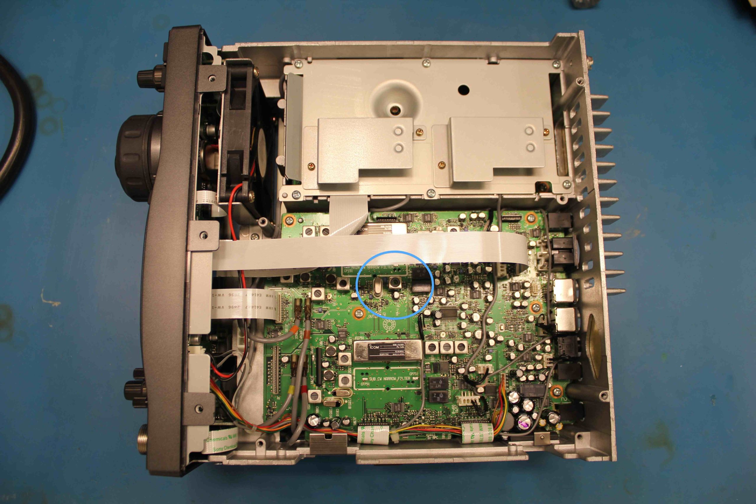
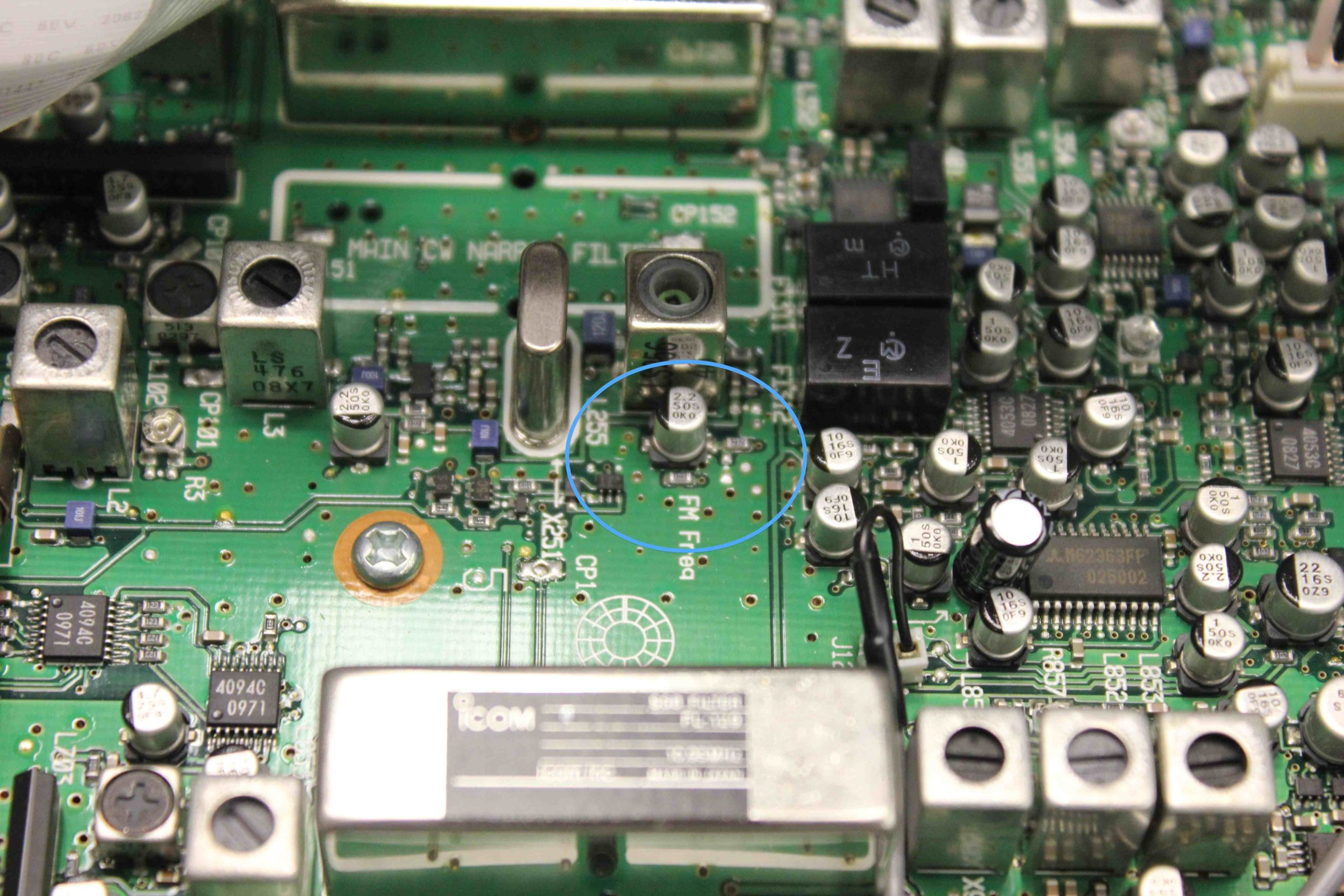
Returning to the schematic, I found that the DIN connection ultimately passes through a voltage divider implemented with a pair of resistors (R262 and R1653) before it reaches the FM modulation diode, D253. The comparable low speed path passes through pair of resistor as well (R1668 and R262). R1653 was much higher at 10K than the matching divider resistor R1668. I changed R1653 to 2.7K and the modified 910 can do much higher deviation, a max of ~ 8.5 KHz, through the 9600 data path. Photos from the modification work are below.
